
Erection & industrial installation
Equipment Support Structure Fabrication & Erection
Frames, skids, racks and gantries designed for the load, the vibration and the movement the equipment actually produces — fabricated in our shop, erected on your plant.
What this service covers
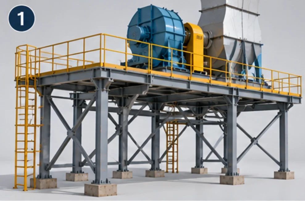
Equipment support structures are the fabricated steel frames, skids, saddles, racks and gantries that carry the machines, ducts, pipework and conveyors inside a plant, designed as part of the equipment installation rather than as a building. They are needed wherever a fan, blower, vessel, conveyor or pipe run has to be held at a height, kept clear of vibration, or given room to move thermally. AKEN designs the support to the equipment loads, fabricates it in its own shop at Hirakud and erects it on site, which means a frame can be re-made on a level floor when a vendor drawing arrives one revision late, instead of being argued about at height.
A support structure is a load path with a purpose. It carries the dead weight of the equipment and its contents, the live loads of the material passing through it, wind on whatever the equipment presents to it, and — on anything with a rotating part — a dynamic load that a static calculation alone does not describe. Getting the steel to carry the weight is the easy half. The other half is making sure the support does not resonate with the machine it holds, does not fight the pipe that runs through it, and does not put the equipment nozzle in bending when the line heats up.
That is why the useful input to a support design is not a weight but a set of vendor drawings. A fan comes with an allowable vibration level, a withdrawal space for the impeller, and a base frame with a specified number of feet. A vessel comes with a support arrangement, a design temperature and an allowance for expansion. A pipe run comes from a stress analysis that fixes where it is anchored, where it slides and where it is guided. A frame drawn without those is a frame that will be cut and re-welded on site.
AKEN works both ways round. Where the client has a vendor drawing and a design basis, we fabricate and erect to it and raise the questions that matter — access, movement, vibration, nozzle load. Where the client has the equipment but no support design, we take the loads from the vendor documents and design the frame, then fabricate and erect it under the same contract. Some of the work is not a new structure at all: it is a bracket, a saddle or a set of rail steel inserted into an existing plant around machinery that carries on running.
Scope of work
What we actually carry out under this service. Anything outside this list is quoted as a separate line rather than absorbed into a lump sum, so you can see what you are paying for.
- Structural design of the support to the equipment loads — dead, live, wind, seismic, vibration and thermal movement acting together
- Vendor drawing review for support points, allowable nozzle loads, permitted movement, withdrawal space and the access a fitter will need
- In-house fabrication of columns, beams, brackets, base plates, stiffeners, gussets and anchor bolt assemblies
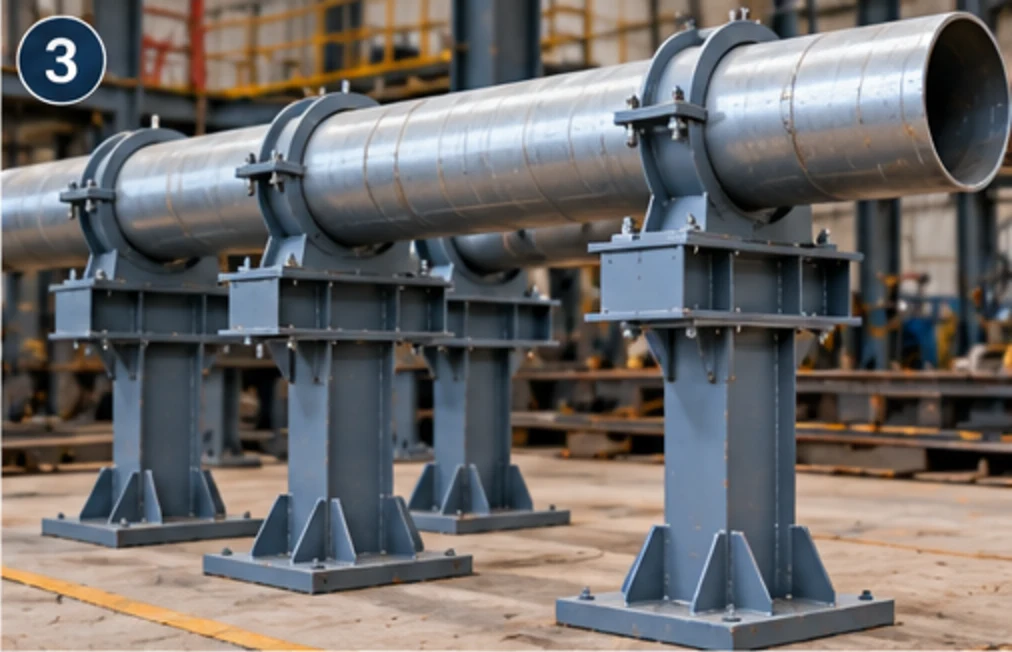
- Pipe racks and sleeper supports, set to the pipe shoe heights and the anchor, guide and slide arrangement the stress analysis calls for
- Fan, blower and duct support frames with the isolation or anti-vibration provisions the equipment specification requires
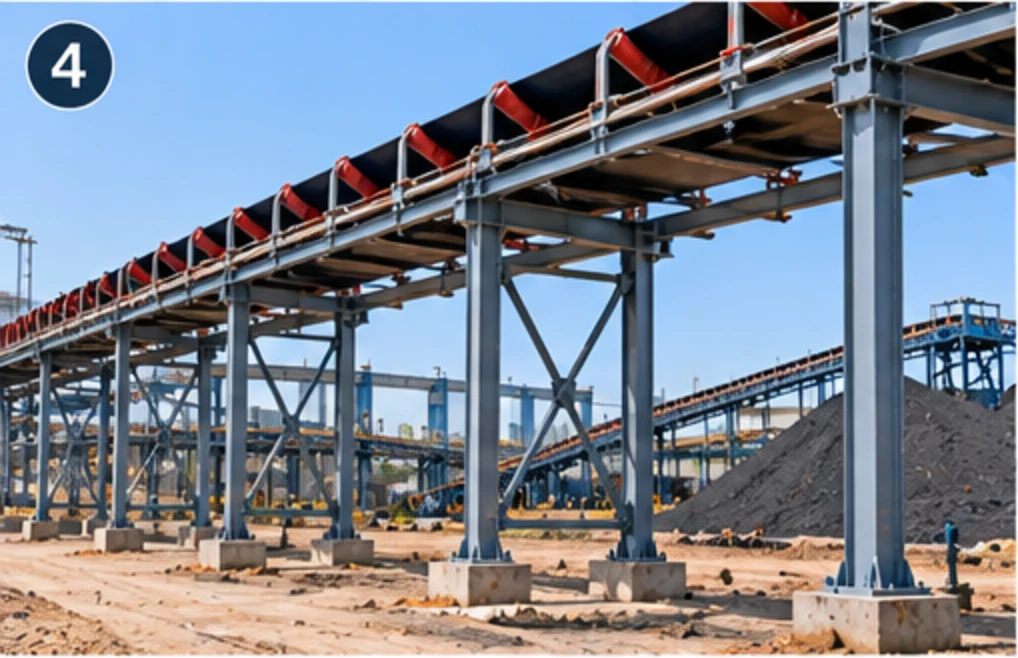
- Conveyor gantries, trestles, transfer point structures and the walkways over them
- Vessel skirts, saddles, support rings and leg arrangements, including the sliding end where a hot vessel has to grow
- Anchor bolt setting out for new foundations, and post-installed anchor design where the support goes into existing concrete
- Access steel — ladders, platforms, handrails and toe boards — taken to the points where the equipment is actually maintained
- Surface preparation and painting, with a system selected for the plant atmosphere rather than a default
Technical capability
Materials, components and methods. Where a figure would be quoted, the governing factor is named instead — a diameter or a tonnage is a design outcome, not a catalogue item, and the number only means something alongside the loads behind it.
- Design basis
- Loads, load combinations and allowable stresses taken from the project specification and the code the plant is designed to, agreed before detailing starts
- Vibration control
- Support stiffness and mass proportioned so the frame does not sit close to the running frequency of the machine it carries, with isolation where the specification asks for it
- Thermal movement
- Sliding, guided and fixed supports placed so a hot line or a hot vessel grows where it is designed to, and the movement is not transferred into an equipment nozzle
- Connection design
- Bolted where site assembly requires it, welded where stiffness does, with base plates, stiffeners and anchorages detailed to the calculated reactions
- Fabrication
- Cutting, drilling, fit-up and welding under cover, with a dimensional check at fit-up so a frame arrives square rather than being corrected on site
- Anchorage
- Cast-in anchor bolts on new work, and post-installed mechanical or chemical anchors in existing concrete where no new pedestal can be built
- Access and maintenance
- Platforms, ladders and handrails arranged around the parts that get serviced, with the withdrawal space for impellers, couplings and seals kept clear
- Surface protection
- Blasting and a coating system chosen for the environment the steel sits in — a fertiliser or coastal plant needs a different system from a dry warehouse
How the work is executed
- 01
Loads and vendor drawing review
Equipment weights, centres of gravity, support points, allowable nozzle loads and movements are collected from the vendor documents. The access and withdrawal spaces the maintenance team needs are settled here, because they are structural dimensions, not finishing details.
- 02
Design and detailing
The frame, connections, base plates and anchorages are designed to the agreed basis, and the arrangement is checked against the plant around it — the crane hook path, the pipe route and the walkway widths included.
- 03
Fabrication and trial fit
Members are cut, drilled and welded in our shop and trial-fitted where the geometry is complex. Holes are drilled from the drawings rather than after arrival on site, so the only thing left to do at height is assemble.
- 04
Setting out and erection
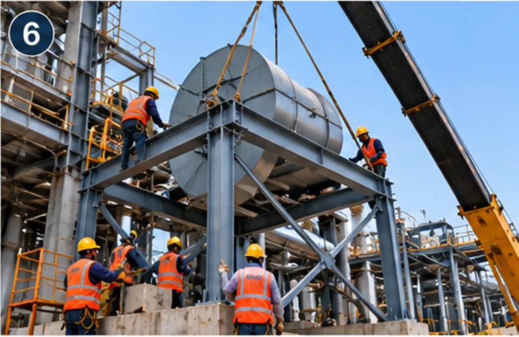
Anchor positions and levels are checked, the frame is erected to a lift plan, plumbed and bolted, and the equipment is landed onto a support that has been proved level and true first.
- 05
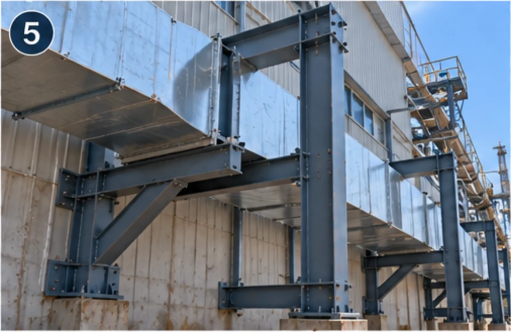
Equipment setting and handover
The machine is shimmed and aligned on the frame, isolation and pipe supports are fitted where specified, paint is touched up, and the structure is handed over with its drawings and reaction schedule.
The work, step by step
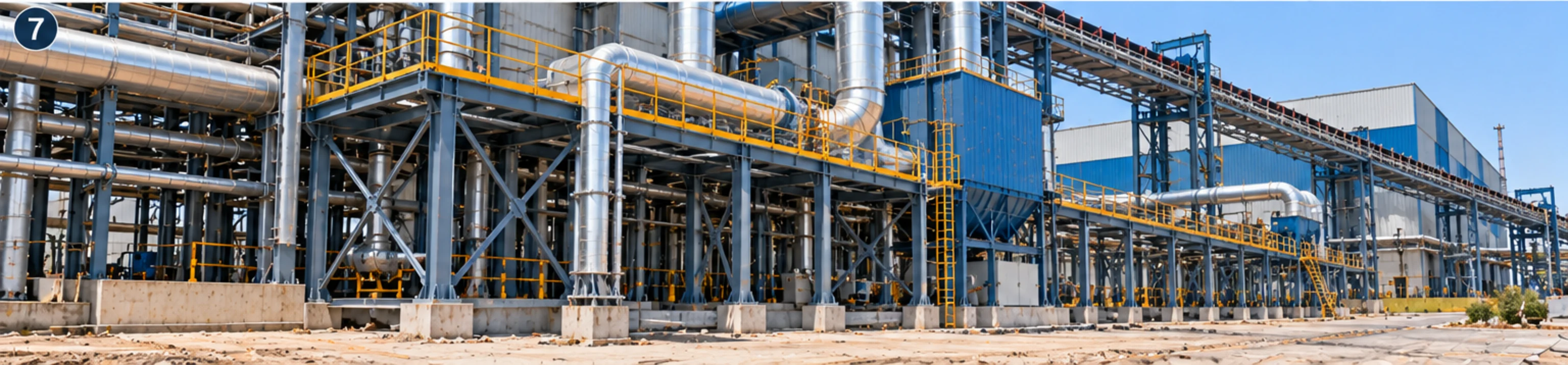
Illustrative images showing the sequence and the type of work involved. They are not photographs of a specific completed AKEN project — for those, see the project photographs.
01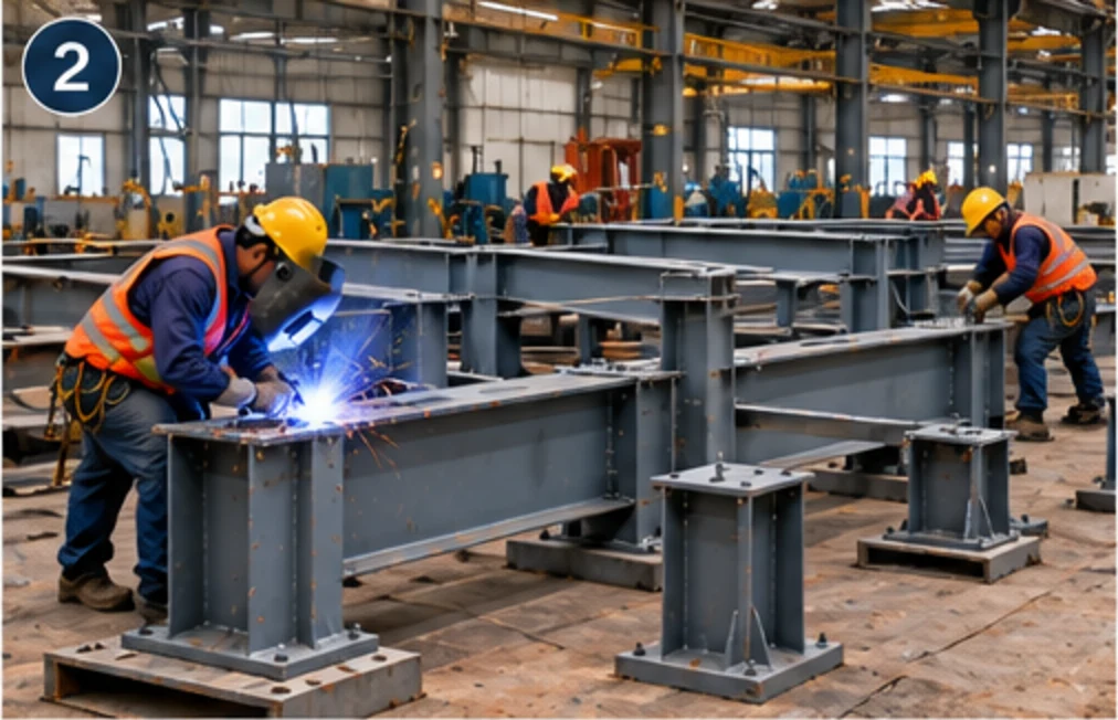 02
 03
 04
 05
 06
 07
Where this is used
We work for plant and procurement teams, EPC contractors and owner-operators across power, cement, mining, manufacturing, warehousing and infrastructure. Much of it is inside a running plant, which sets the terms of the job.
- Fans, blowers and duct support frames
- Pipe racks, sleeper supports and cable racks
- Conveyor gantries and transfer trestles
- Vessel and tank support rings and saddles
- Pump and compressor skid base frames
- Dust collectors and bag filter structures
- Cooling tower and heat exchanger supports
- Equipment platforms inserted into existing plants
Why AKEN
Designed, made and built by one party
The designer, the fabricator and the erector are the same company under one contract. When a support does not clear the pipe route or the hook path, nobody has to be persuaded whose problem it is.
Structure follows the equipment
We design from the vendor drawing and the stress analysis, so the frame allows the movements the equipment needs instead of assuming everything is rigid. That is what keeps a nozzle out of bending.
Shop work where it is cheaper
Cutting, drilling and welding happen on a level floor under cover. Fitting at height costs several times what fitting in the shop costs, and it is rarely done as well.
Fits the plant around it
Most of our supports go into bays that already contain working equipment, existing pipework and a fixed crane route. The arrangement is checked against those before fabrication, not discovered at erection.
In-house fabrication capacity
Brackets, rail steel, saddles and modification pieces get made without waiting on an outside vendor sheet — which matters most when a shutdown window is already fixed and short.
Our safety controls are set out in full at site safety, including the photographs we withdrew because they showed unsafe work.
FAQ
Equipment Support Structures: questions buyers ask
What counts as an equipment support structure?
Any fabricated steel whose job is to hold equipment in place rather than to form a building: fan and duct frames, pump skids, vessel saddles and skirts, pipe racks, conveyor gantries, dust collector supports and equipment platforms. The distinction matters because a support is designed around one specific machine — its feet, its weight, its movement and its access — while a shed is designed around an envelope and a span.
Who designs the support — the equipment vendor or you?
Sometimes the vendor supplies a support drawing with the machine, and then we fabricate and erect to it. Often the vendor supplies only the machine data — weight, support points, allowable movement, nozzle loads — and the support has to be designed. We take the loads from those documents and design the structure to the project specification. Either way, we raise the access, movement and clearance questions rather than assuming them.
How do you deal with vibration from a fan or blower?
By treating the dynamic case as a design input rather than a nuisance to fix afterwards. The frame has to be stiff enough that its own frequency does not sit close to the running frequency of the machine, and where the specification asks for it, isolation mounts are introduced between the equipment and the structure. A frame that is merely strong enough but too flexible will carry the machine fine and still transmit vibration into the building.
Why do some pipe supports have to slide?
Because a pipe that carries a hot fluid grows when it heats up, and that growth has to go somewhere. A pipe fully anchored at every support would push its expansion into the nearest equipment nozzle, which is what the nozzle design allows for least. So one point is fixed, intermediate supports slide or guide, and expansion joints or loops absorb what is left — pipe supports and expansion joints exist so that thermal movement is not transferred into equipment nozzles.
Can you fabricate to a drawing supplied by our vendor?
Yes, and we will review it before fabrication starts. Vendor support drawings occasionally miss the plant around them — a handrail that fouls a cable tray, a brace where the walkway has to go, a base plate that does not clear a plinth. Raising that on a drawing is a red line; raising it after the frame is fabricated is a cutting and re-welding job at height.
How is a support structure fixed to the floor?
On new work the anchor bolts are cast in, set out from the fabrication drawing and checked before concreting. In an existing plant where there is no pedestal to build, the support is fixed with post-installed anchors designed for the actual reactions and the concrete strength that is there. Base plates are then grouted so the load goes into the foundation through the whole plate rather than through a few shim points.
Do you supply only, or fabricate and erect as well?
Both, but the combined scope is the one we recommend. Fabrication and erection under one contract means the frame is made by the party who has to fit it, and the tolerance question is answered internally. Where the client erects with their own contractor, we fabricate to drawing and inspect at despatch, and the fit-up responsibility sits with the erector.
How do you allow for maintenance access in the frame?
By deciding it at the design stage, from the vendor manual: which part gets serviced, what has to come out, which way it comes out, and how much room a fitter needs with tools. Impeller withdrawal space, coupling access, seal replacement clearance and a place to land a chain block all become structural dimensions — a platform added after erection is always the expensive way to get them.
Can a support structure be added around running equipment?
Yes, and it is common in expansion and retrofit work. It usually means prefabricating as much as possible in the shop, bringing it in through an existing opening, and limiting site work to bolted connections and the few welds that need a shutdown window. Hot work near live equipment is done under the client permit, with a fire watch and shielding, and often in a window the client sets.
How is the steel protected against corrosion?
With a coating system chosen for the atmosphere the structure sits in, on a surface that has been prepared properly first. A coastal or fertiliser plant, a cement plant with alkaline dust and a covered warehouse need different systems, and a support under a duct that drips condensate needs a different detail as well as a different paint. The specification sets the system; blasting and DFT checks make it real.
Related services
Next step
Have an industrial project in mind?
Discuss your requirement with AKEN. Send the site location, the scope and the date you are working towards, and we will tell you what we need to quote it properly — usually a site visit, scheduled within 72 hours.
+91 82800 76864 · contact@aken.firm.in